282 defines the full outside diameter of the brake disc across its widest circular edge.
 Mounting face kept clear for fit


Replacement brake service scenes
The images show the brake disc at a wheel hub during workshop and wheel-off service. The exposed hub, nearby brake hardware and lifted vehicle context show how the component relates to replacement, alignment and access.
 Brake hardware visible beside disc
 Disc aligned on exposed wheel hubMounting face kept clear for fit
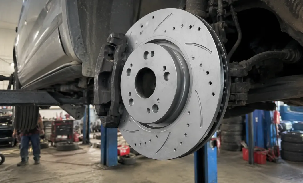 Wheel removed for disc accessBrake hardware visible beside discDisc aligned on exposed wheel hub
Real-car highway chase at golden hour—on-road braking feel verified after fitment.

282 defines the full outside diameter of the brake disc across its widest circular edge.
47 measures the total height from the lower disc surface to the top of the raised center hub.
23 indicates the full thickness of the vented braking section measured between both outer faces.
64.2 specifies the diameter of the central opening used for accurate hub positioning and fit.
5+2+2 identifies the verified mounting-hole arrangement around the brake disc center section.

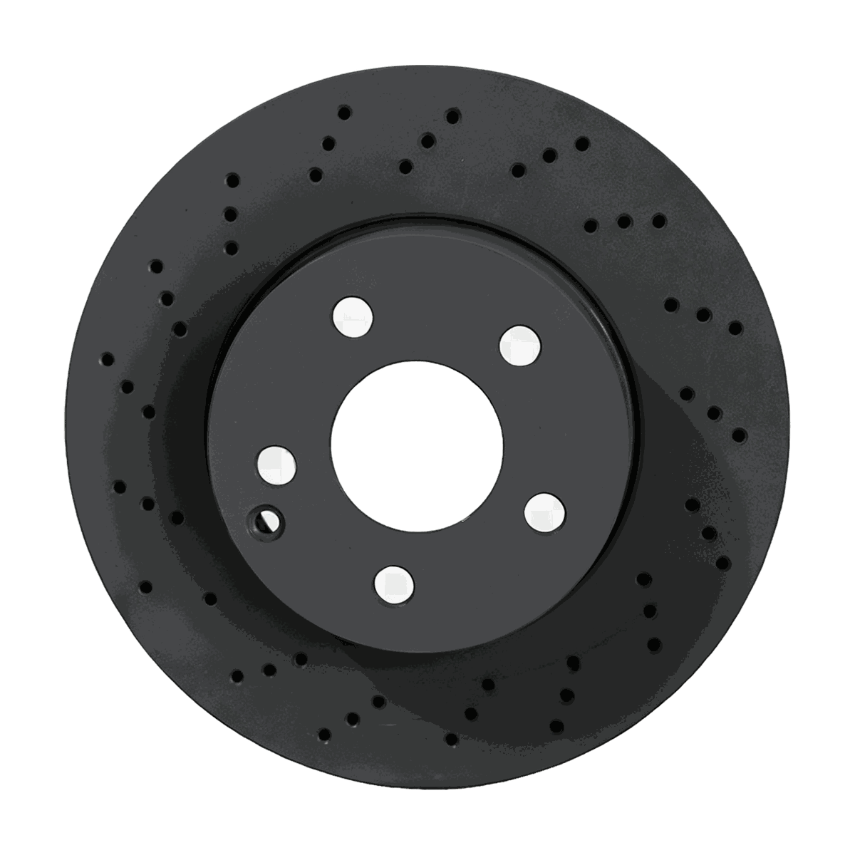
yh20343 drilled-and-slotted disc—arcs and holes clear heat/debris, 5-lug, OE 45251SDCA00 gray iron.
00:28yh20343 drilled-and-slotted disc—arcs and holes clear heat/debris, 5-lug, OE 45251SDCA00 gray iron.
00:30Highway brake-test cut—real-car motion with overlays that show a quick, stable stop after fitment.
00:23Thick corrugated cartons with desiccant and manuals, film-sealed then palletized for steadier outbound protection.
Real on-site records from our factory, offering a practical view of our production capability and delivery readiness.
We centrally purchase equipment, test the data and the machine, then publish the models that clear our review. You get a shorter path from "could work" to a quote your team can act on.
Our team is ready to advise you on the best product configuration and procurement plan.
info@eascoutia.com400 158 5899Match it by the dedicated model field and the confirmed outer diameter, height, thickness, center bore and hole configuration.
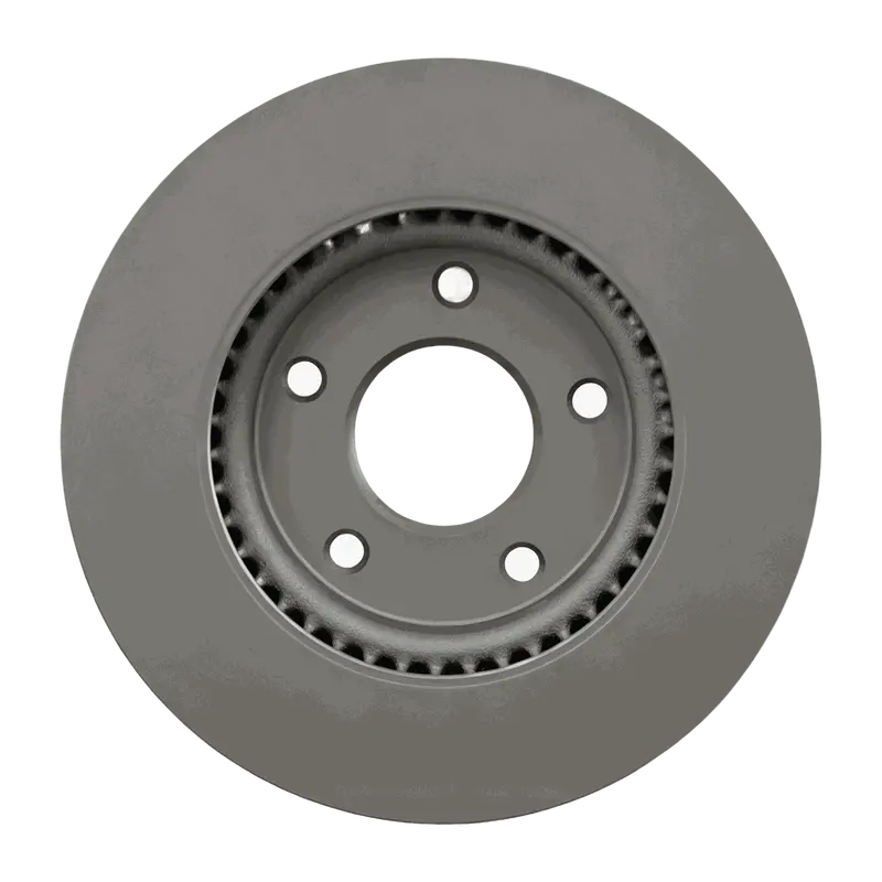
The visible face combines curved slots with drilled holes, so it should be compared with the required replacement style.
The confirmed hole configuration is 5+2+2 holes, shown in the parameter image and reflected in the dimension diagram.
No separate finish option is listed, so procurement should follow the designated color requirement in the purchase plan.
No separate accessory or core configuration material is specified for this item in the confirmed product information.
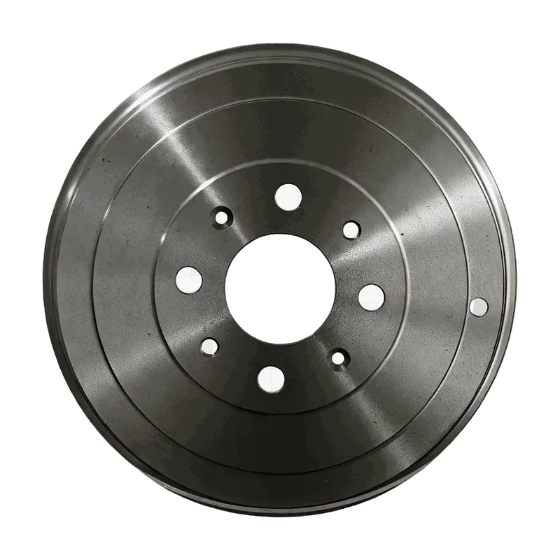
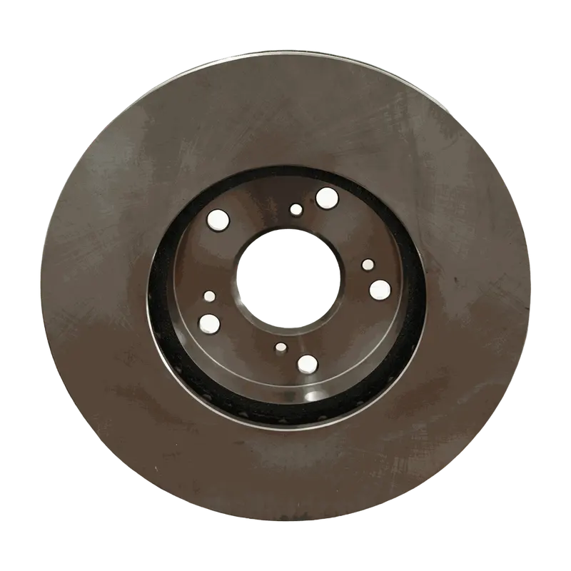
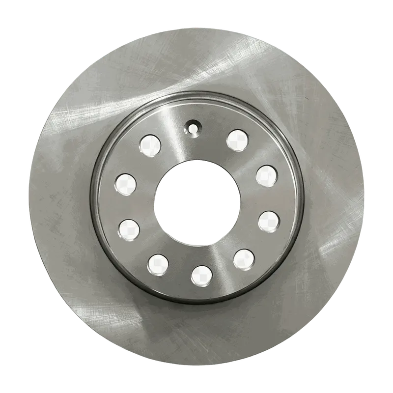
 Simplified explanation
