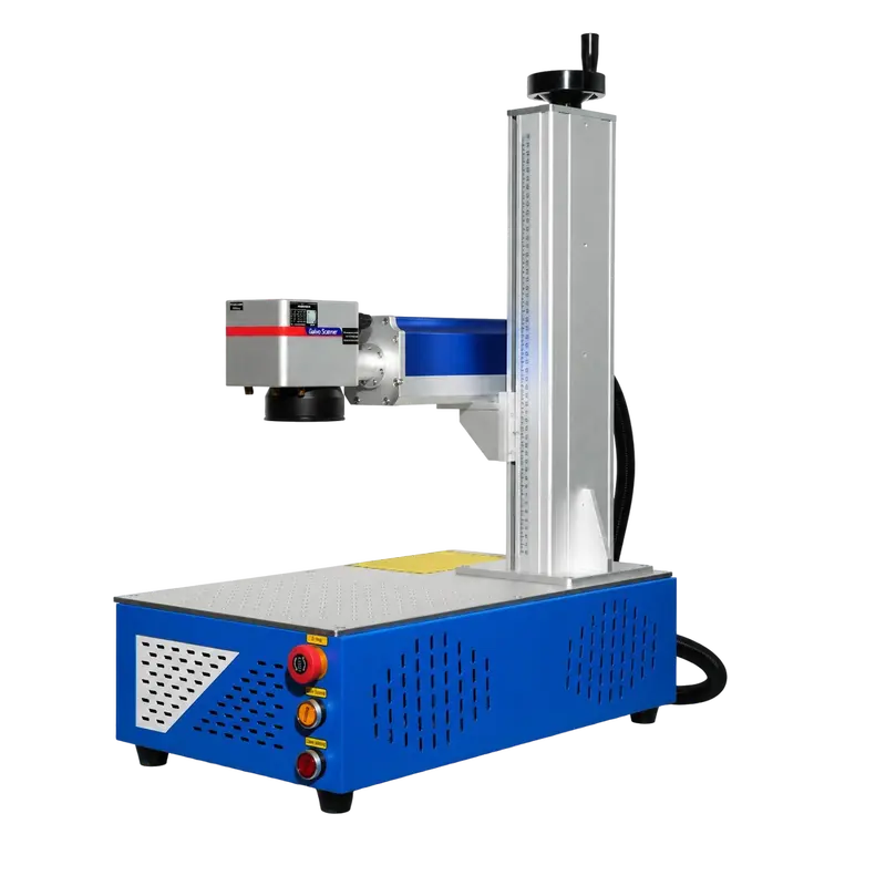
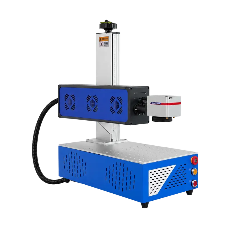
Main blue cabinet with vented panels and stable feet.
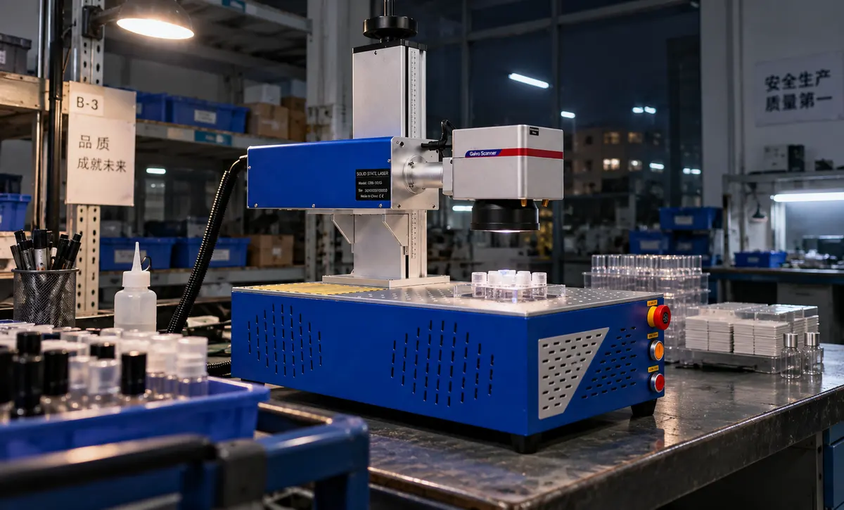 Small precision parts are positioned beneath the marking head within an industrial workstation operating under night-shift lighting

Flexible Marking Across Precision Production and Traceability Workflows
The four application scenes show the machine at precision plastic component marking, electronics traceability, glass and cosmetic component marking, and night-shift precision-parts workstations. Each setup presents small workpieces positioned within a practical production, inspection, or identification workflow.
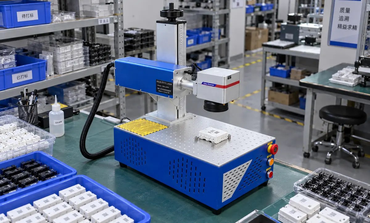 Glass or cosmetic-related components are presented at the marking workstation for controlled product identification applications
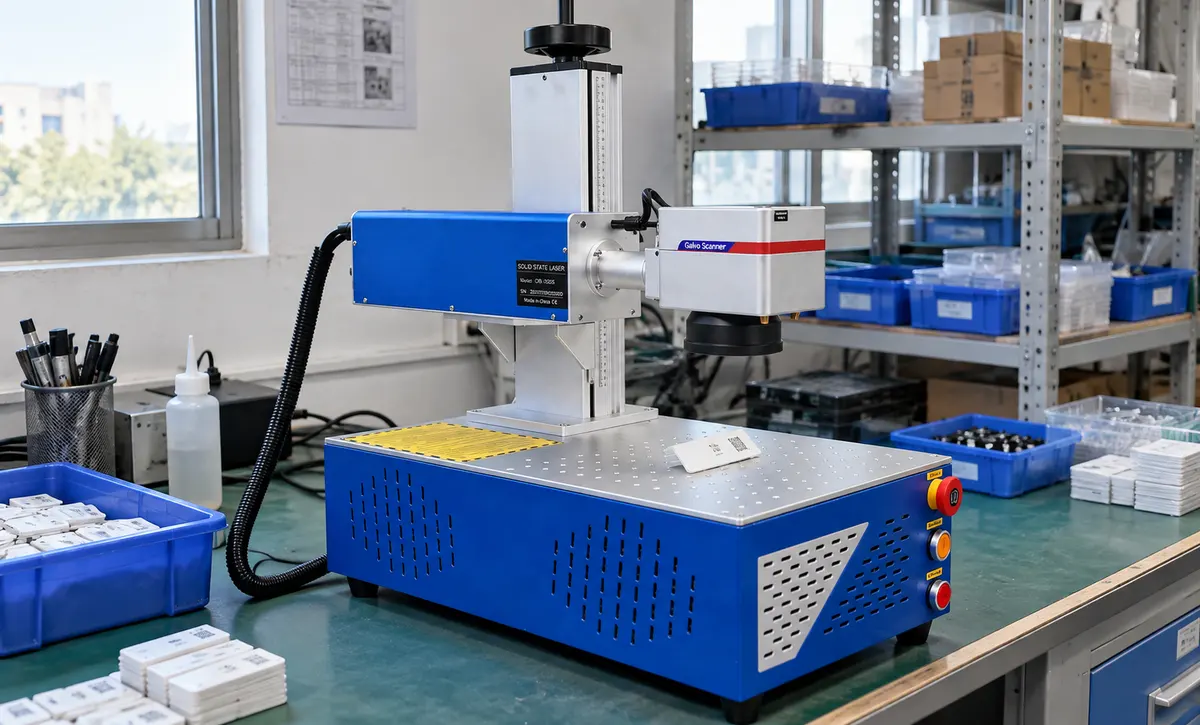 Small plastic components are positioned at a dedicated marking workstation for product identification and precision marking tasksSmall precision parts are positioned beneath the marking head within an industrial workstation operating under night-shift lighting
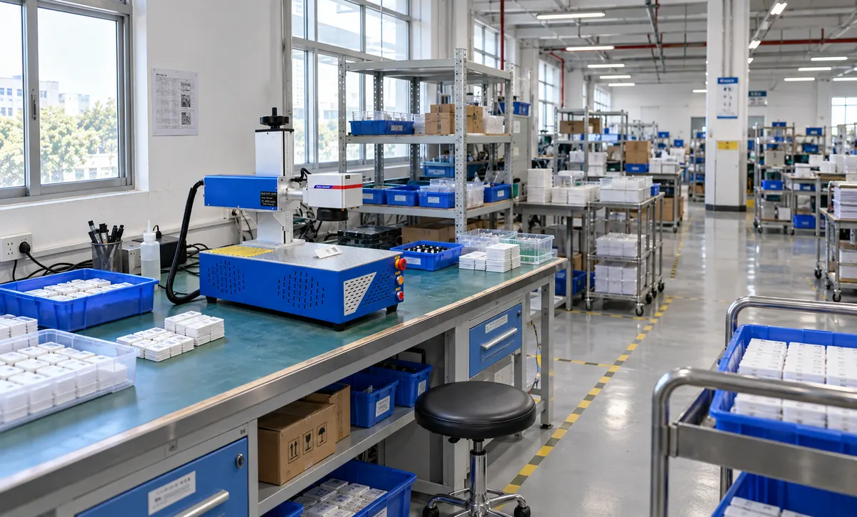 The machine is placed within an electronics production environment where components are organized for identification and traceability markingGlass or cosmetic-related components are presented at the marking workstation for controlled product identification applicationsSmall plastic components are positioned at a dedicated marking workstation for product identification and precision marking tasks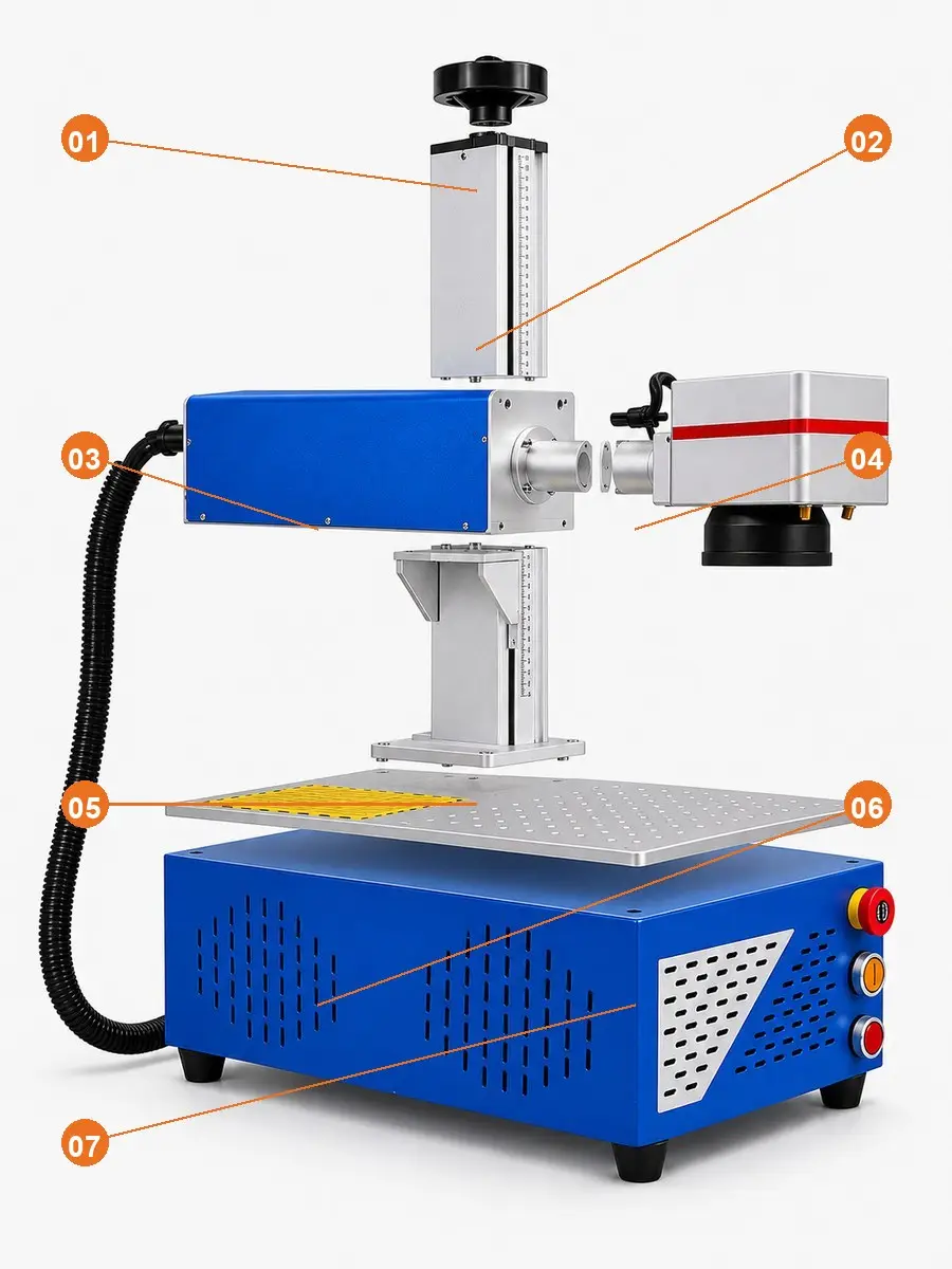
Main blue cabinet with vented panels and stable feet.
Perforated fixture table for accurate part placement.
Blue horizontal housing mounted across the upper frame.
Vertical column for height positioning.
Scanner head aligned with the marking work area.
Three colored operating buttons on the front control area.
Flexible hose and visible mounting connection for routing.
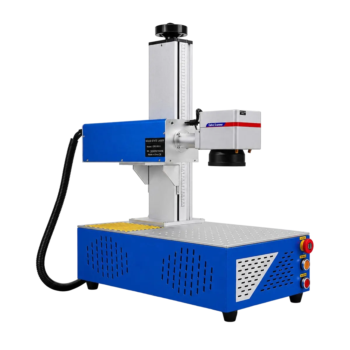
Appearance display of DU series. Integrated frame with stable structure and clean streamlined design.
00:19Appearance display of DU series. Integrated frame with stable structure and clean streamlined design.
00:33Operation demonstration of DU series. Responsive control system and high cutting precision for various metal materials.
00:12Export wooden case packaging for DU series laser equipment, reinforced, shockproof and moisture-proof for ocean container transportation.
Real on-site records from our factory, offering a practical view of our production capability and delivery readiness.
We centrally purchase equipment, test the data and the machine, then publish the models that clear our review. You get a shorter path from "could work" to a quote your team can act on.
Our team is ready to advise you on the best product configuration and procurement plan.
info@eascoutia.com400 158 5899The provided applications include precision plastic components, electronics traceability, glass and cosmetic-related components, and precision parts marking.
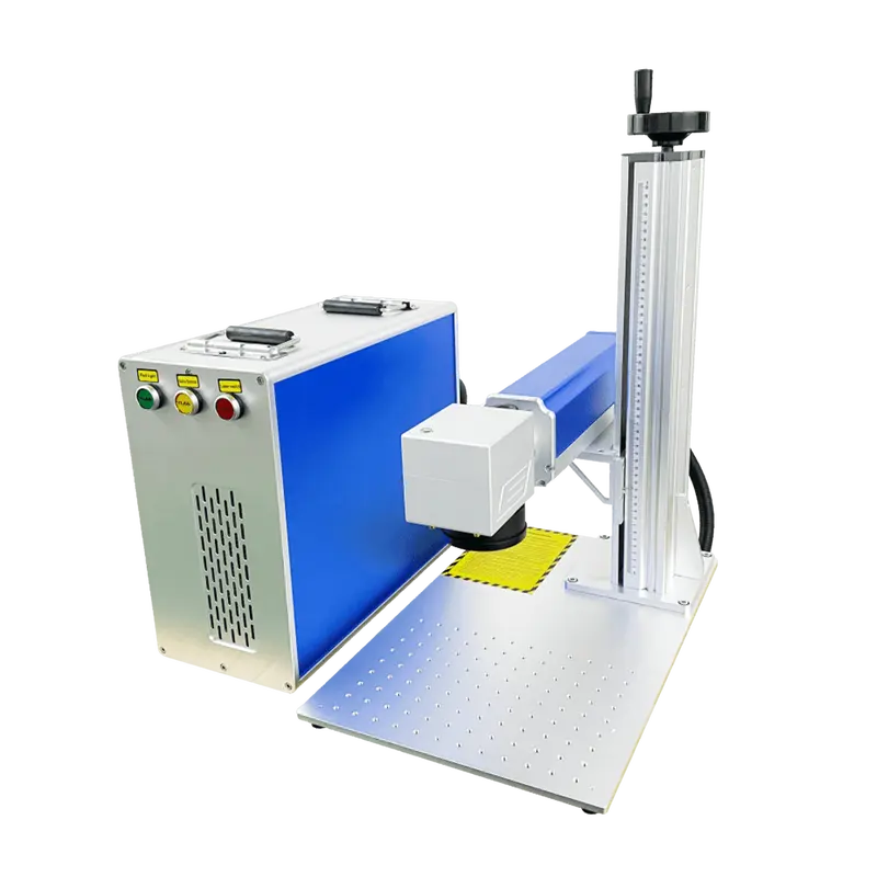
Yes. The machine has a desktop configuration intended for placement on a suitable production or marking workbench.
The visible vertical column and handwheel provide a mechanical structure for adjusting the marking-head position relative to the work surface.
These materials are included in the provided application scenarios. Exact compatibility should still be confirmed according to the specific material, surface, and required marking result.
Confirm the actual workpiece material, component dimensions, marking content, required result, and production workflow before selecting the appropriate configuration.
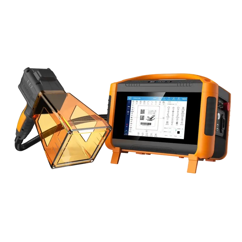
 Simplified explanation