Securely holds the operating linkage at the top of the galvanized fire damper frame.
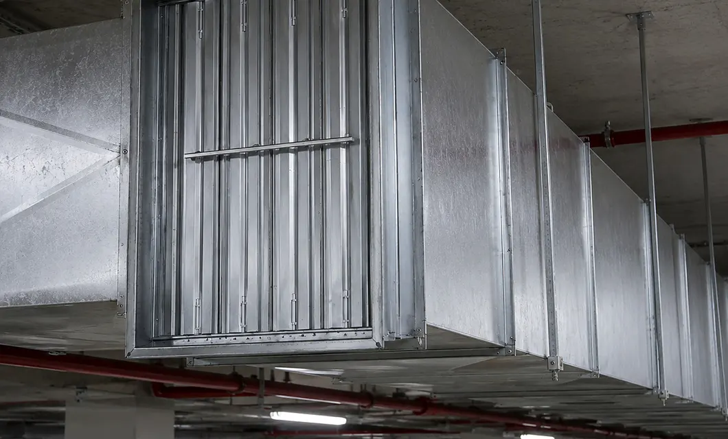 Service corridor damper supports smoke control along duct routes.


Automatic Isolation at Fire Boundaries
At protected ventilation boundaries, this galvanized fire damper uses linked blades and a thermal release mechanism to isolate airflow during a fire response. The scenes show placement in fire ducts, boundary walls, service corridors, and heat-sensitive points where reliable closure and coordinated smoke-control planning are required.
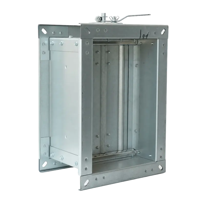
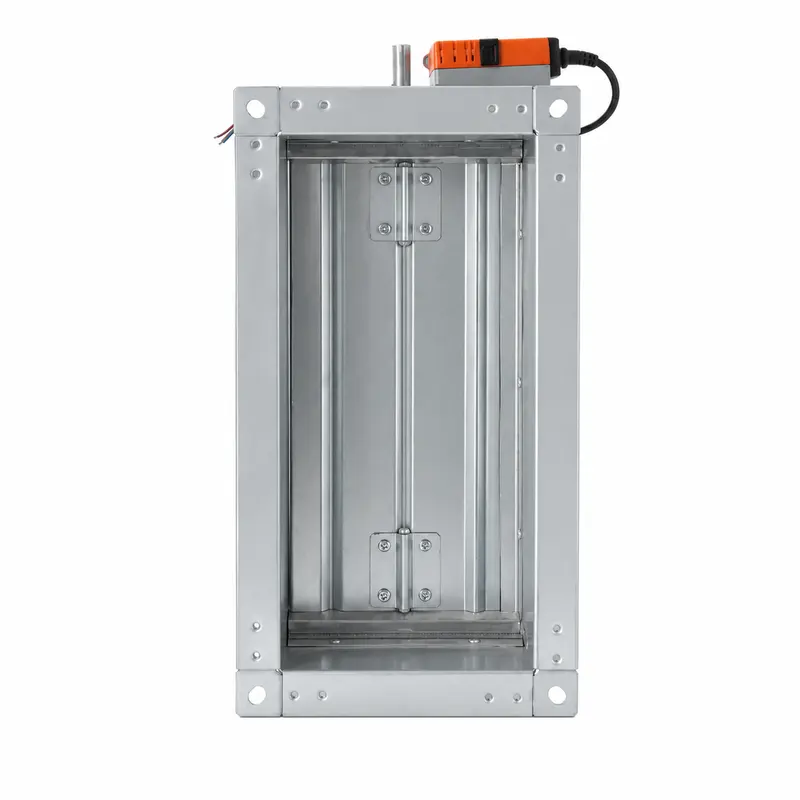
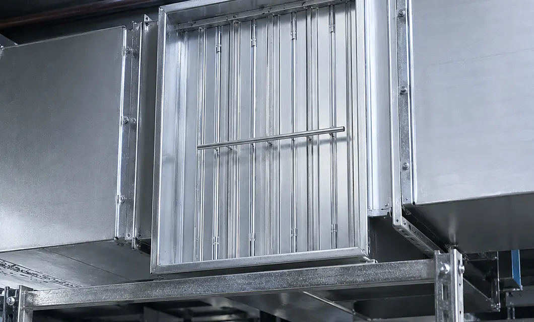 Fire damper in ductwork is ready for automatic closure at the vent.
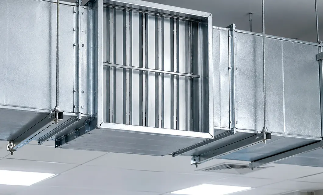 Damper section isolates airflow at a rated fire boundary.Service corridor damper supports smoke control along duct routes.
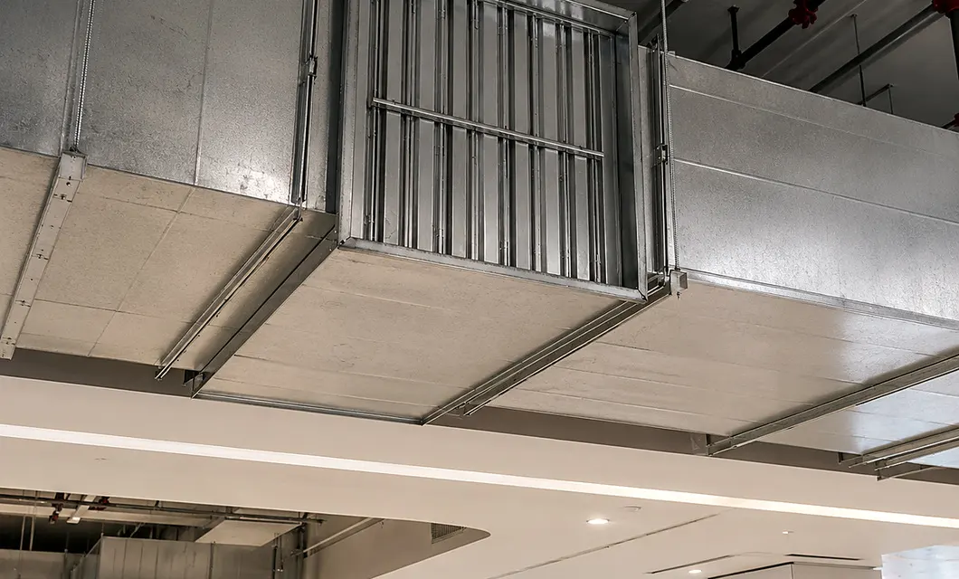 Heat-responsive damper protects the duct opening during emergencies.Fire damper in ductwork is ready for automatic closure at the vent.Damper section isolates airflow at a rated fire boundary.
The actuator moves multiple blades closed together, progressively sealing the visible passage within the damper frame.
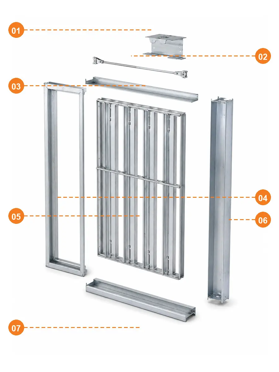
Securely holds the operating linkage at the top of the galvanized fire damper frame.
Transfers closing motion from the release mechanism to the connected blade bank.
Supports the upper frame joint and keeps the complete blade assembly correctly aligned.
Forms the rigid galvanized housing for secure installation at the fire duct boundary.
Closes together to isolate airflow when the fire response mechanism is activated.
Protects the blade edges and maintains the rectangular damper body geometry in service.
Completes the lower frame connection and securely stabilizes the assembled damper body.
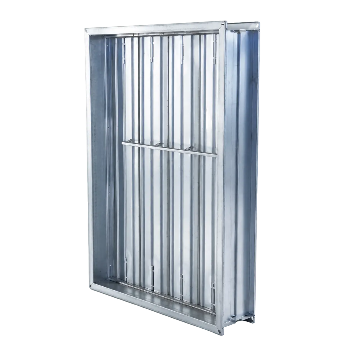
Shows the fire damper actuator and the linked opening and closing movement of its blades.
Our team is ready to advise you on the best product configuration and procurement plan.
info@eascoutia.com400 158 5899Frame dimensions should match the duct opening, required airflow, wall or floor boundary, and the approved fire-control design.
Install the frame squarely at the specified boundary with accessible operating parts, using the approved fixing and sealing method.
The galvanized finish follows the supplied construction; other material or surface requests require confirmation before production.
Selection should follow the fire design, duct size, installation boundary, airflow direction, control linkage, and access requirements.
An initial reply is provided within 24 hours, while technical selection questions are checked against the project fire-control details.



 Simplified explanation