Supports the manual operating handle and anchors it firmly to the damper frame during operation.
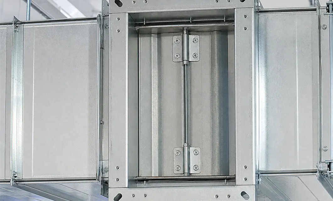 Manual airflow setup keeps the service corridor duct balanced.


Direct Manual Airflow Adjustment
This manual damper provides direct airflow adjustment through an external locking handle and coordinated blade bank. The scenes show use in ductwork, plant rooms, service corridors, and factory ventilation where operators need a fixed setting, clear access, and stable air-volume control without a powered actuator.
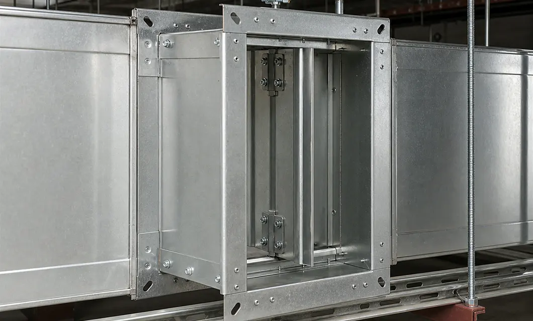 Manual damper handle sets airflow directly at the duct section.
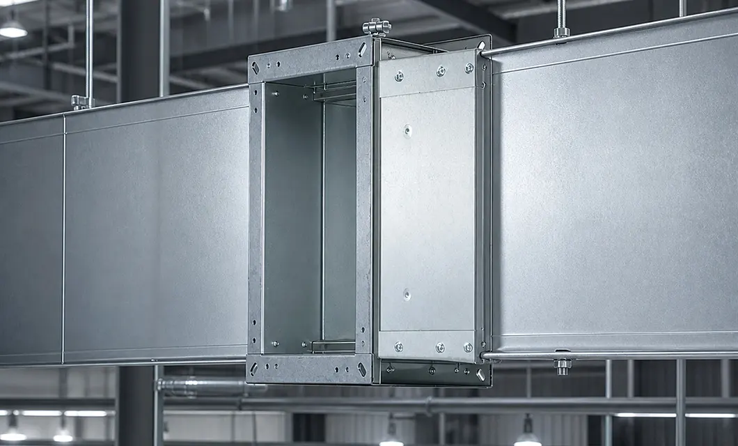 Locking handle holds the damper position inside the plant room.Manual airflow setup keeps the service corridor duct balanced.
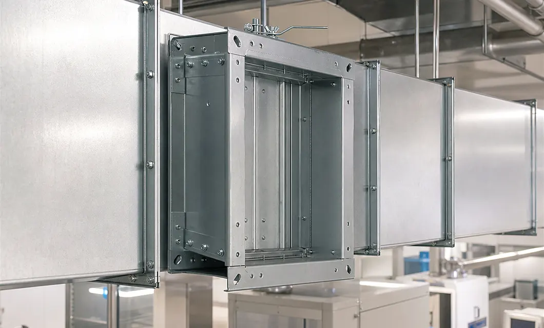 Simple handle control adjusts factory ventilation at the duct line.Manual damper handle sets airflow directly at the duct section.Locking handle holds the damper position inside the plant room.
The close-up demonstration shows the operator turning the adjustment handle, with the manual setting sequence clearly visible.
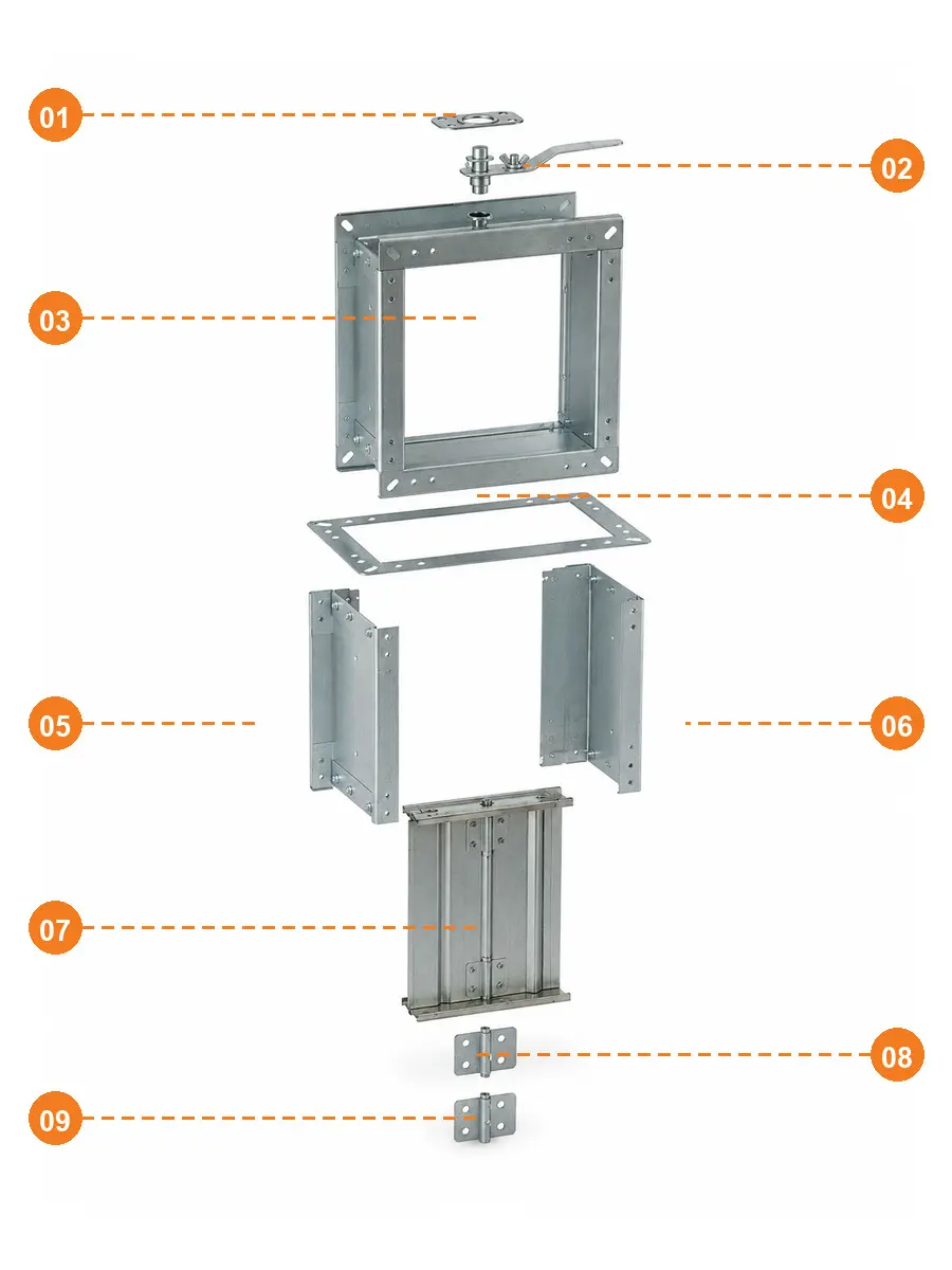
Supports the manual operating handle and anchors it firmly to the damper frame during operation.
Sets the blade angle by hand and holds the selected airflow position securely during operation.
Provides the main galvanized rectangular housing for installation inside ductwork.
Forms the perimeter fixing surface used to connect the damper to the air duct during operation.
Supports the blade pivots on the left and protects the linked internal mechanism.
Supports the opposite blade pivots and preserves the rigid valve body alignment.
Rotates together under handle control to set the required ventilation airflow during operation.
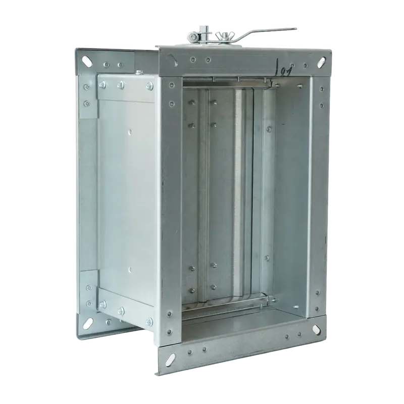
Shows the manual damper blades and the complete operating process of its adjustment handle.
Our team is ready to advise you on the best product configuration and procurement plan.
info@eascoutia.com400 158 5899Frame dimensions should match the duct opening, required air volume, available handle clearance, and connection arrangement.
Install the body squarely in the duct with the handle accessible, then set and lock the blades after airflow balancing.
Body material may be discussed in galvanized steel, carbon steel, or stainless steel for the confirmed application.
Selection should consider duct size, airflow, material, blade orientation, handle access, installation space, and operating conditions.
An initial response is provided within 24 hours, with material and sizing details reviewed against the submitted requirements.


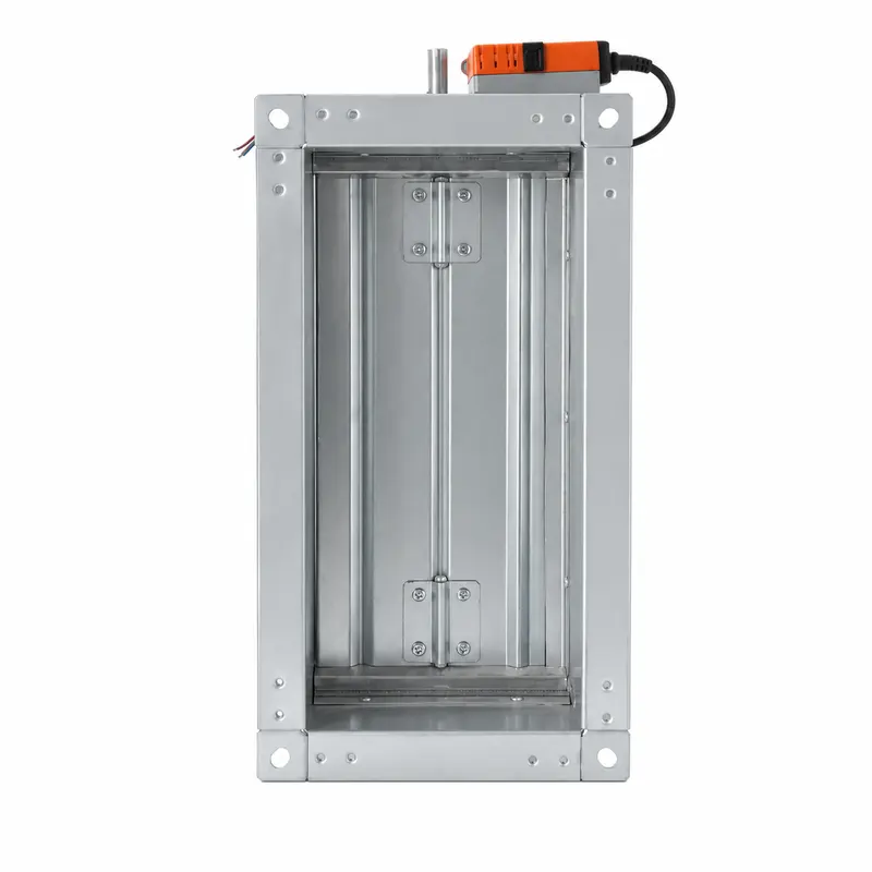


 Simplified explanation