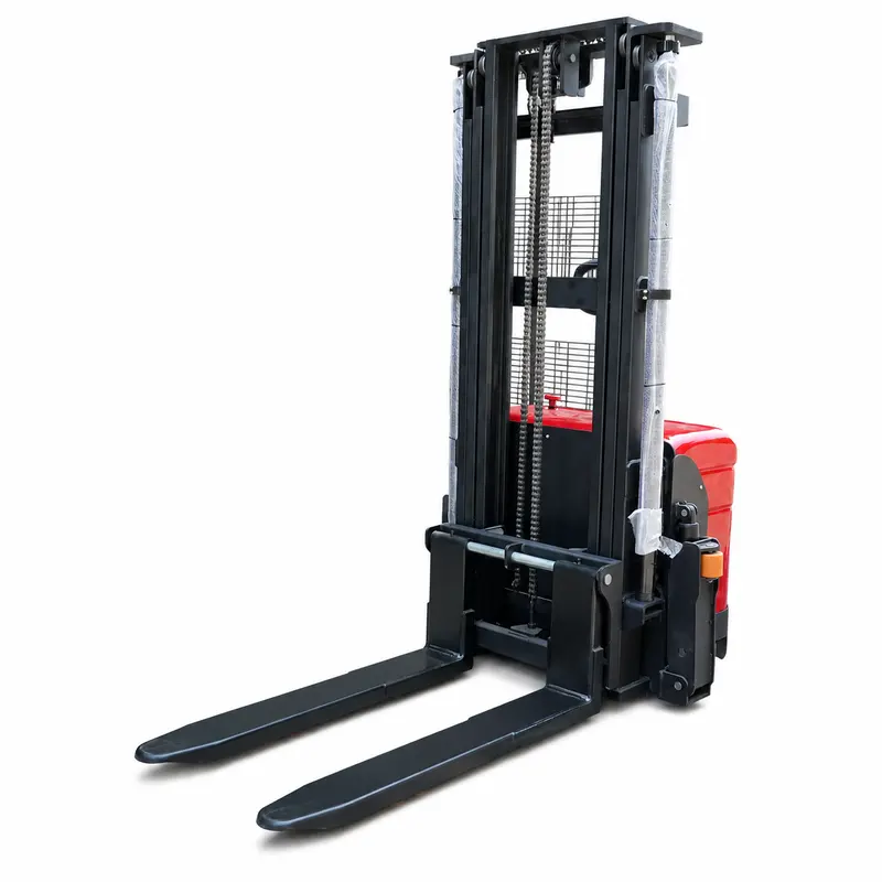
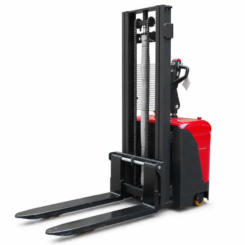
High‑strength dual‑column mast with guide rails bears main lifting loads to ensure stable and reliable cargo handling performance.
 Positions Materials Beside Workshop Entrances


Rough-Terrain Stacker material handling and positioning
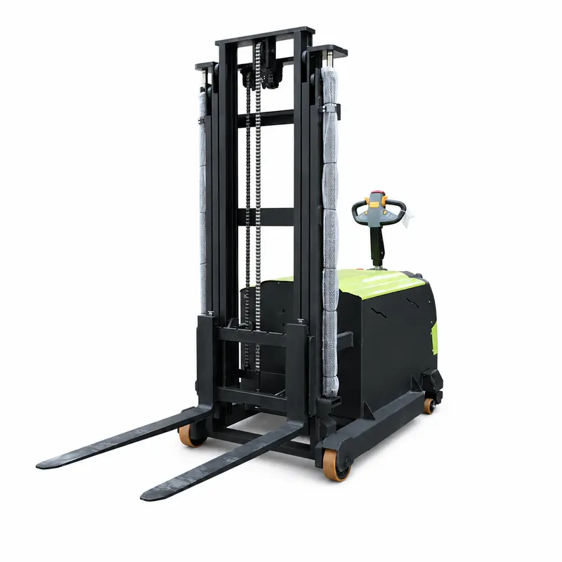
This model supports controlled pallet lifting, short-distance movement and placement in prepared warehouse, loading and production areas. The visible fork path and operator controls support deliberate alignment and repeatable material flow without unsupported performance claims.
 Handles Pallets on Outdoor Worksites
 Moves Loads Across Uneven Industrial YardsPositions Materials Beside Workshop Entrances
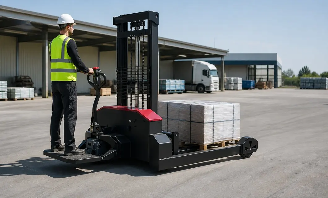 Transfers Pallets Between Yard ZonesHandles Pallets on Outdoor WorksitesMoves Loads Across Uneven Industrial Yards
With a rated capacity of 1.5T and 1070mm forks, electric lifting connects with stand-on transport, reducing manual lifting,.

High‑strength dual‑column mast with guide rails bears main lifting loads to ensure stable and reliable cargo handling performance.
Composed of cylinders, chains and sprockets, it supplies power for mast to realize smooth cargo lifting and lowering movements.
Connects mast and forks to secure cargo, cooperating with lifting mechanism for pallet handling and stacking operations.
Red‑black outer shell protects internal electric, hydraulic and drive parts against impact and facilitates routine inspection & maintenance.
Black steel frame supports mast, power system and wheels, acting as the core base for whole‑machine mounting and force bearing.
Integrates travel, lifting and steering controls with compact layout for operators to maneuver equipment and handle cargo efficiently.
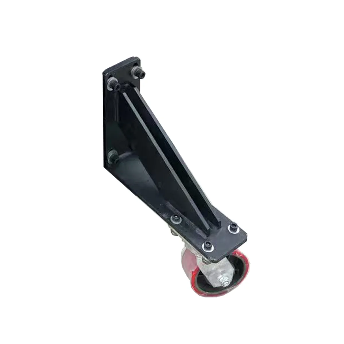
Bottom auxiliary wheels support fork and machine weight, offering flexible rolling to improve stability and reduce traveling resistance.
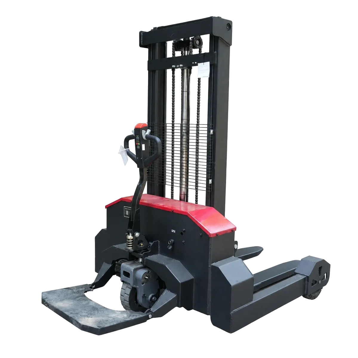




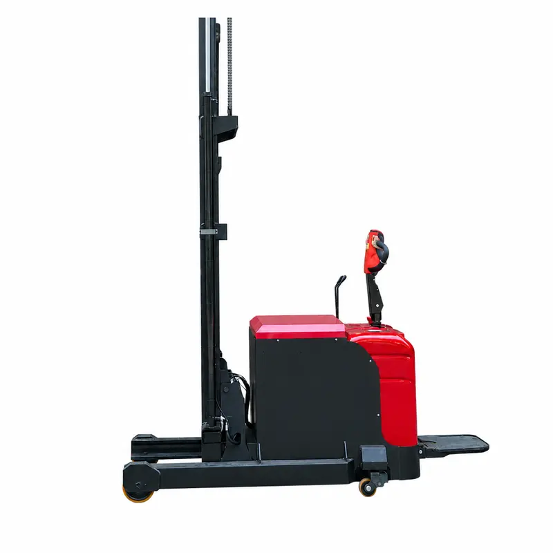
Multiple angles highlight the machine, mast, forks, body and controls.
00:26Multiple angles highlight the machine, mast, forks, body and controls.
01:04Shows pallet handling, fork lifting, steering, travel and handle control.
00:33Machines braced inside containers and shipped by road and sea — tracked all the way to your site.
Real on-site records from our factory, offering a practical view of our production capability and delivery readiness.
We centrally purchase equipment, test the data and the machine, then publish the models that clear our review. You get a shorter path from "could work" to a quote your team can act on.
Our team is ready to advise you on the best product configuration and procurement plan.
info@eascoutia.com400 158 58991. It is commonly used for industrial parks, logistics routes, worksites and managed fleet operations, subject to the selected model and site conditions.
2. Match payload, dimensions, axle or tire specification, powertrain, route and regulatory requirements to the actual workload and operating environment.
3. Confirm model, color, payload, axle or tire specification and optional equipment, then verify the response time and any special requirements.
4. Prepare delivery inspection, approved registration where applicable and scheduled tire, brake and fluid checks; follow the manual for operation, inspection and routine maintenance.

 Simplified explanation
