

The floor-standing cabinet supports the machine and retains the enclosed cutting assembly.
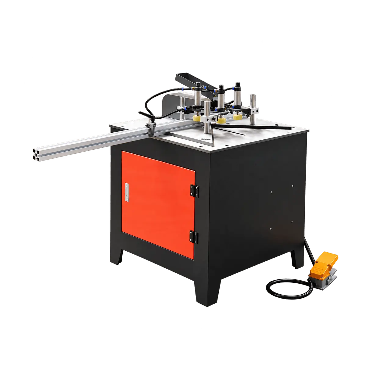
Wooden Frame and Trim Workstation
From Stock Positioning to Clamping
Support a wooden profile on the guide rail, adjust the existing positioning stop, and locate the stock on the worktable. The scenes show profile alignment, stop adjustment, foot-pedal operation and pneumatic clamping in a frame workshop. The rail, fences and pressure feet form the visible stock-handling arrangement.
- 1. Corner Cutting - Frame Profile Alignment
- 2. Length Positioning - Rail Stop Adjustment Before Cutting
- 3. Pedal Operation - Foot Pedal Controlled Clamping
Specifications & Structural Decomposition
Product Structure Diagram
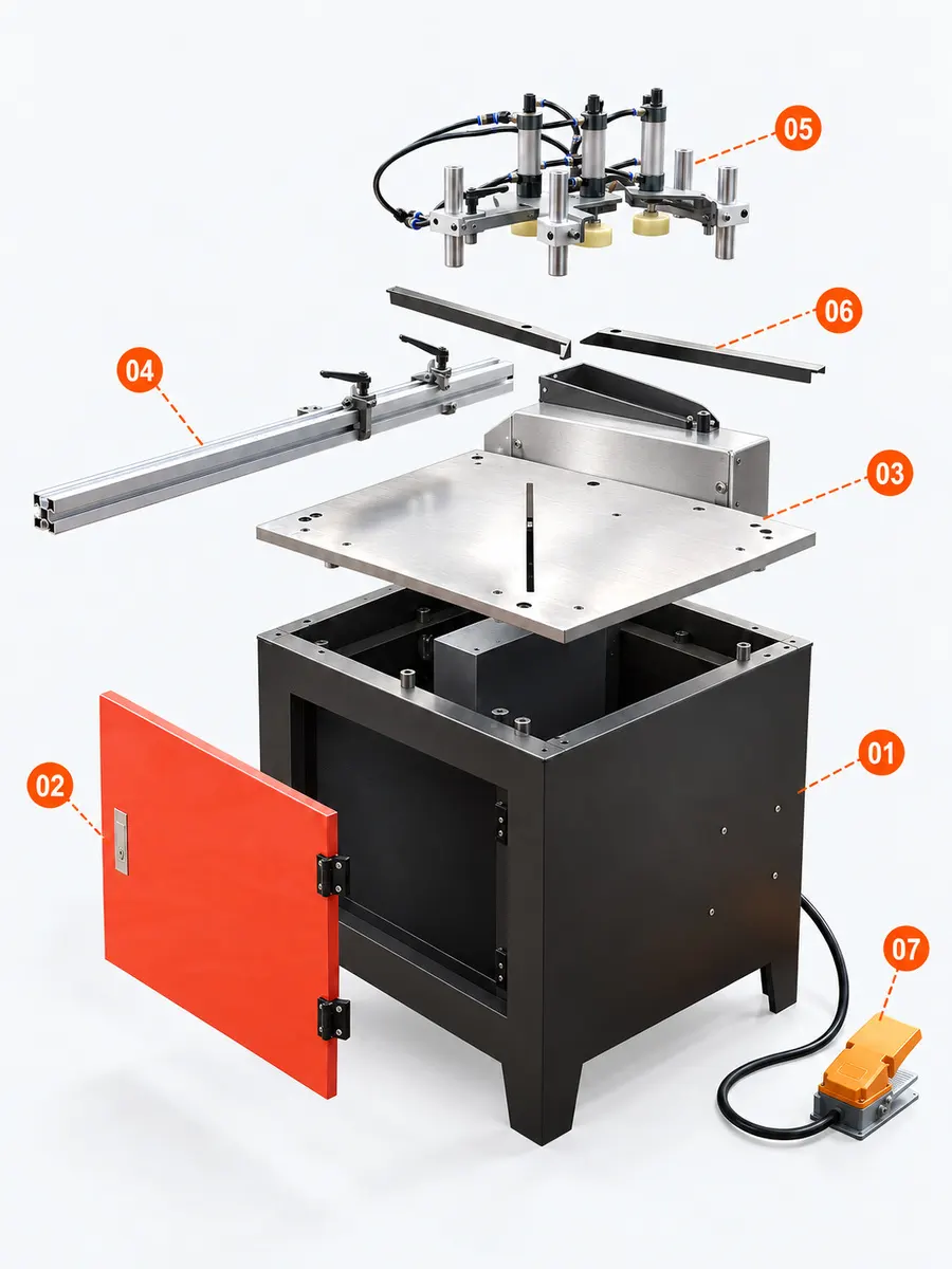
- 01 Cabinet and Enclosed Cutting Unit
- 02 Front Access Door
The front access door is shown separately from its original cabinet opening.
- 03 Worktable and Rear Guard
The metal worktable and rear guard form the visible support around the cutting area.
- 04 Long Guide Rail
The long guide rail extends from the worktable to support and locate profile stock.
- 05 Pneumatic Clamp Group
Grouped cylinders and pressure feet hold the workpiece against the working surface.
- 06 Positioning Fence Pair
Two positioning fences relate the stock orientation to the central cutting area.
- 07 Foot Pedal and Cable
The floor pedal and its connecting cable form the foot-operated control group.
General information
General instructions
 Simplified explanation
Core Component Details
We're here to help
Our team is ready to advise you on the best product configuration and procurement plan.
info@eascoutia.com400 158 5899Frequently Asked Questions (FAQ)
What stock is it intended for?
It is intended for frame and trim profiles. Confirm the material, profile section and required cutting arrangement for the intended job.
What holds the workpiece?
The visible pneumatic cylinders act through pressure feet above the worktable. They form the machine's workpiece-clamping arrangement.
How is stock positioned?
The worktable uses locating fences, while the extended rail and its positioning stop provide references for placing the profile.
Is a foot pedal provided?
A floor pedal and its connecting cable are shown with the machine. Confirm the operating sequence and installation arrangement before use.
What should I confirm?
Confirm the profile section, cutting angle, electrical supply, compressed-air arrangement and space required for the extended guide.