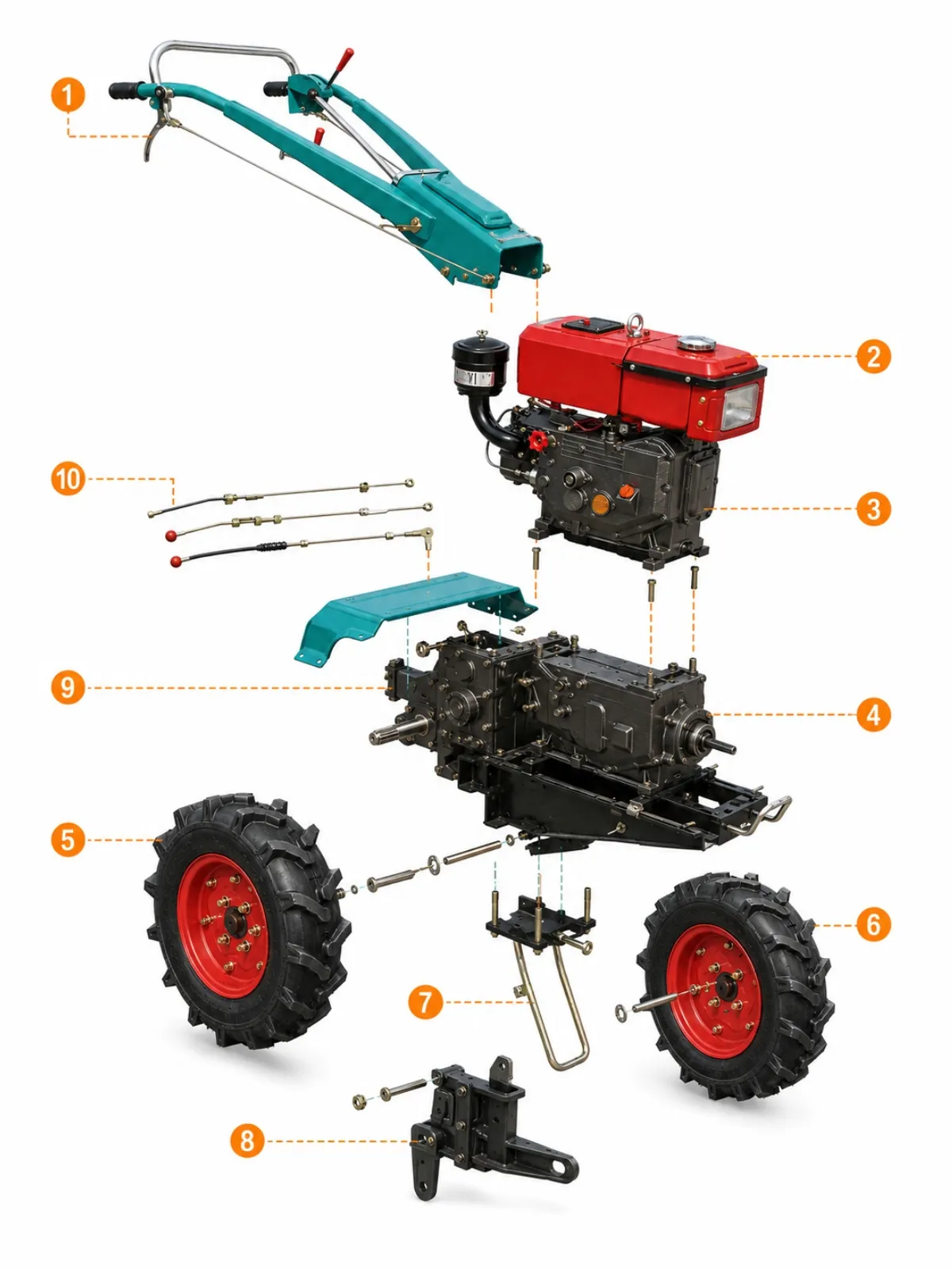
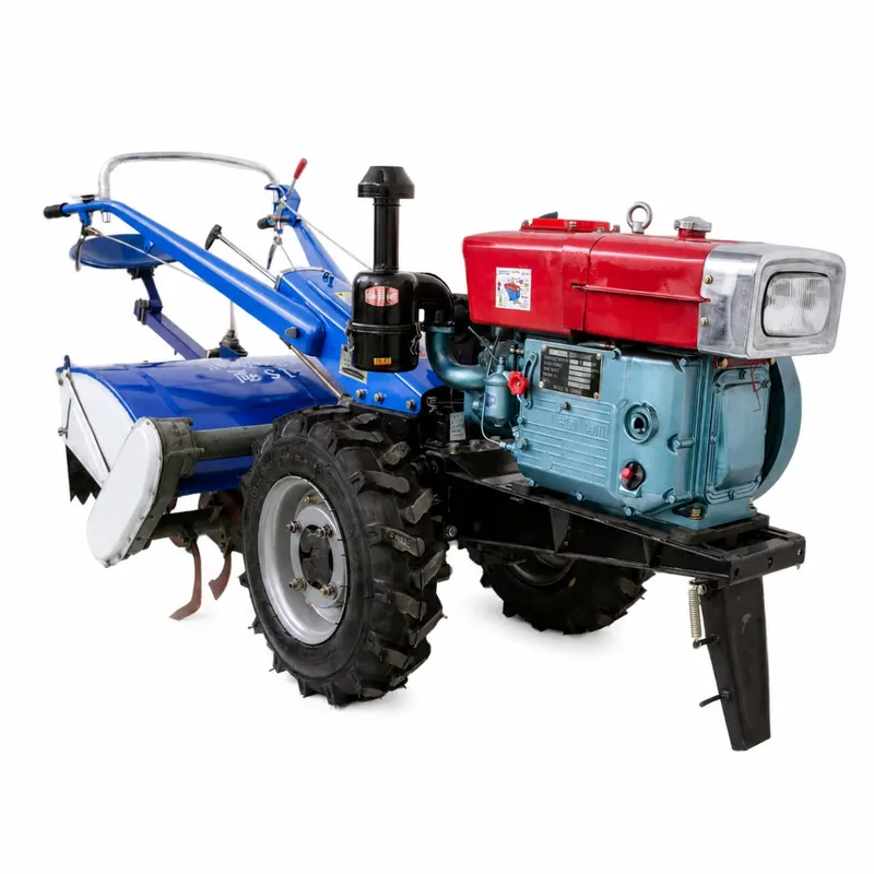
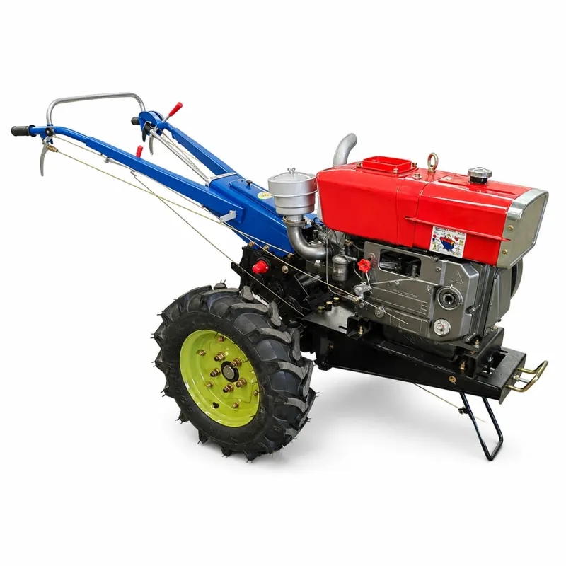
The long handlebar assembly carries the hand grips, levers, and control cables for guided operation from behind.
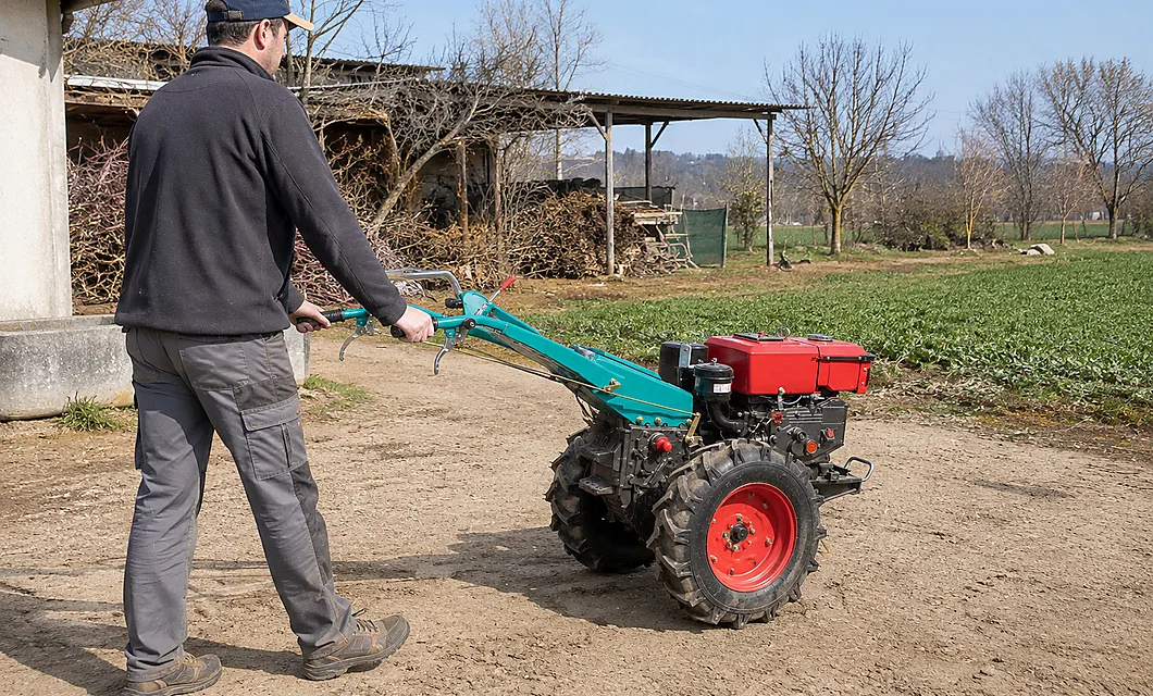 Farm Lane Maneuver - Farm Lane Movement Between Work Areas


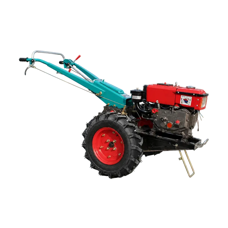
Guided Tractor Work in Prepared Soil
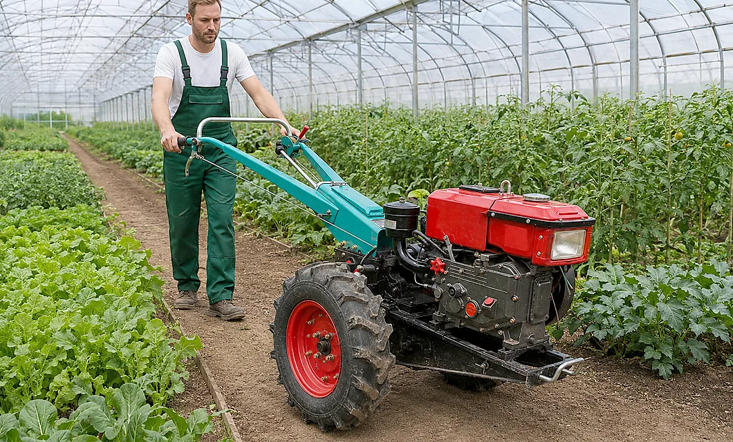
This walking tractor is shown in ordinary field and yard settings with an operator guiding the handlebar from behind. The treaded wheels carry the machine over prepared soil while the rear interface holds the working implement. Suitable work routes, attachment choice, ground condition, and operator clearance should be confirmed for each site.
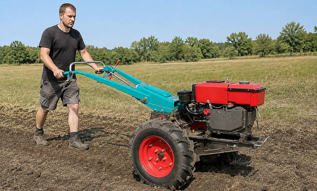 Open Field Work - Open Field Soil Preparation
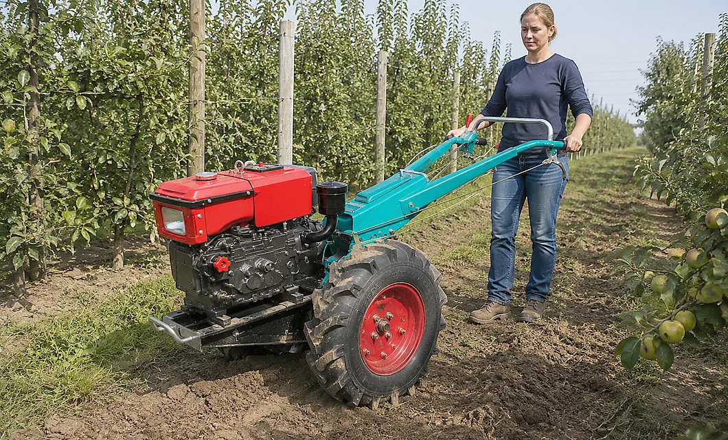 Row Cultivation - Row Cultivation With Guided ControlFarm Lane Maneuver - Farm Lane Movement Between Work Areas
 Implement Setup - Rear Implement Setup Before Field WorkOpen Field Work - Open Field Soil PreparationRow Cultivation - Row Cultivation With Guided Control
The long handlebar assembly carries the hand grips, levers, and control cables for guided operation from behind.
The upper engine and tank module provides the power unit and fuel storage mounted ahead of the chassis.
The engine body encloses the crankcase and visible service points, forming the main drive source for the tractor.
The exposed pulley and belt set transfers engine rotation toward the transmission while remaining accessible for service.
The black gearbox chassis supports the driveline, wheel axles, and rear implement connection in one structural base.
The left treaded wheel mounts to the axle and provides ground contact for steady hand-guided travel.
The right treaded wheel mounts to the axle and works with the opposite wheel to keep the tractor balanced in motion.
Our team is ready to advise you on the best product configuration and procurement plan.
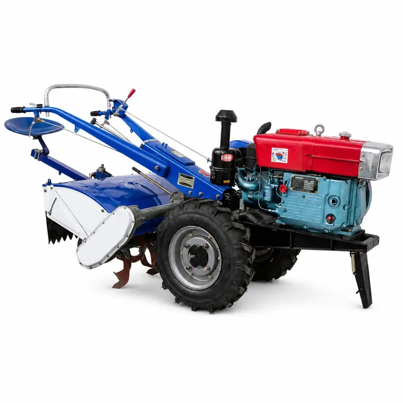
info@eascoutia.com400 158 5899The supplied material shows a hand-guided tractor with a compact engine, two treaded drive wheels, reachable controls, and a rear implement interface. Confirm the exact implement before ordering.
The operator walks behind the machine and uses the handlebar levers to guide its direction and working line. Keep the route clear and confirm control response before starting work.
Power is visibly transferred through the engine, pulley and belt section, then into the transmission chassis and wheel axle. No additional speed or output figures are supplied.
The images support prepared soil, field rows, farm lanes, and yard handling as conservative settings. Actual ground condition and implement clearance still need site confirmation.
Confirm the model field, visible implement arrangement, ground condition, control layout, wheel clearance, and transport or storage method before selection.
 Simplified explanation