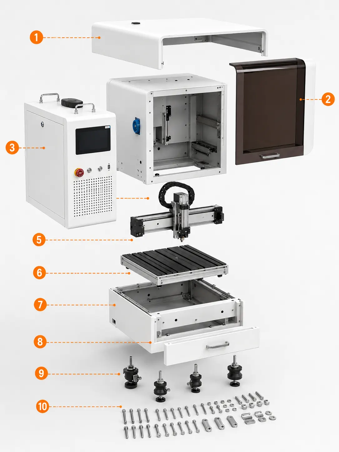
The smoke-brown transparent cover encloses the visible processing area while retaining a clear front observation surface and the original integrated silver handle.
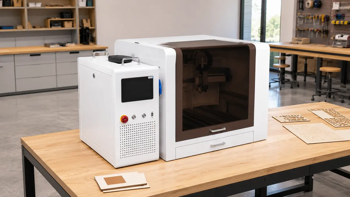 Engineering Training Lab


Workshop Processing and Production-Line Use with Laser cutter GL-40
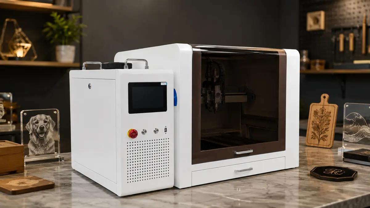
The enclosed GL-40 fits naturally into a jewelry metalworking studio, combining a visible work chamber, separate controls, and a compact bench-friendly footprint. The open safety cover exposes the visible processing area for sample placement, while the separate control cabinet keeps routine laboratory operation organized. The enclosed chamber and separate control cabinet sit naturally in a metalcraft studio, while the accessible lower drawer supports orderly daily use. A side-front view clearly presents the dual-module layout, safety cover, and processing area at a realistic scale for engineering training and sample work.
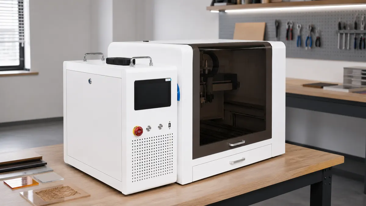 Precision Jewelry Workshop
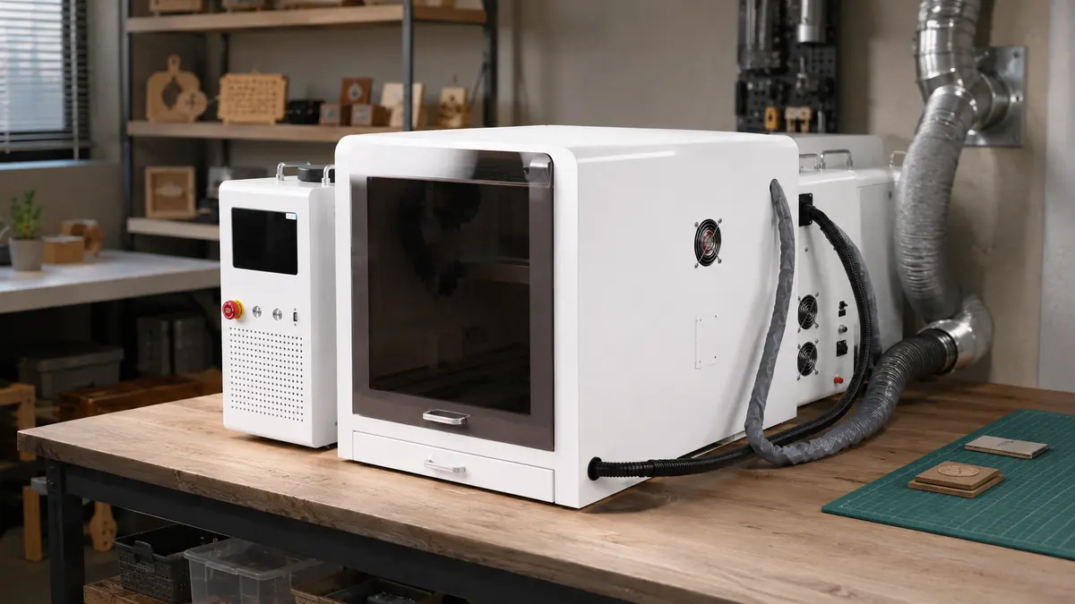 Electronics Prototyping Lab
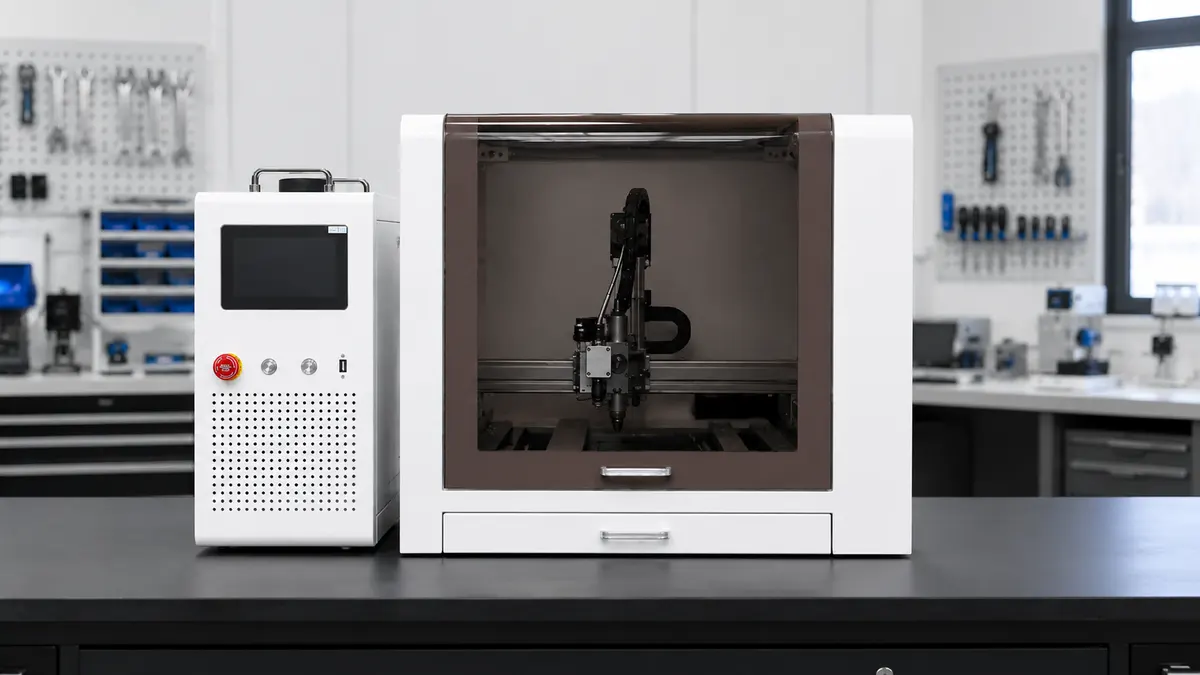 Metalcraft Studio ApplicationEngineering Training Lab
 Gift Customization StudioPrecision Jewelry WorkshopElectronics Prototyping Lab
Integrated touch-screen control panel, one-button start/stop, parameters clearly visible at a glance.
The smoke-brown transparent cover encloses the visible processing area while retaining a clear front observation surface and the original integrated silver handle.
The separate left-side cabinet groups the touchscreen, emergency stop, two control buttons, USB port, ventilation holes, and top carrying handles in one external module.
The white sheet-metal chamber forms the main enclosure around the processing area and supports the safety cover, gantry, workbed, and lower drawer in their original positions.
The visible horizontal beam and carriage guide the laser head across the work area while preserving the confirmed external rail and carriage structure shown in the references.
The central silver laser head includes the visibly confirmed nozzle, adjustment body, fittings, and adjacent carriage connection without adding any hidden internal components.
The dark workbed provides the visible platform for positioning flat samples inside the chamber and remains aligned beneath the gantry and laser head.
The lower front pull-out drawer is a confirmed external module with its original white face panel and silver handle for convenient access beneath the work area.

GL-40 Appearance and Operation. Compact structure, simple operation and stable performance during work.
00:23GL-40 Appearance and Operation. Compact structure, simple operation and stable performance during work.
01:21GL-40 Operation. Easy and flexible operation with stable running for smooth work.
Real on-site records from our factory, offering a practical view of our production capability and delivery readiness.
Our team is ready to advise you on the best product configuration and procurement plan.
info@eascoutia.com400 158 58991. It is commonly used for factories, fabrication shops, production cells and custom-processing workshops, subject to the selected model and site conditions.
2. Match material type, work size, capacity, accuracy, speed, control method, power and extraction needs to the actual workload and operating environment.
3. Confirm model, working area, power, tooling, control system and optional fixtures, then verify the response time and any special requirements.
4. Prepare rated utilities, safe operating clearance, ventilation or dust extraction and operator training; follow the manual for operation, inspection and routine maintenance.
 Simplified explanation